
Use in Fluid Dynamics II lab.
Experimental cababilities of this device include:
➤ Relative changes in the terms of Bernoulli’s equation for converging flow.
➤ Energy losses in converging and diverging flow.
➤ Specific energy relationships for sub-critical flow.
➤ Critical depth and its influences on upstream water levels.
➤ Flow over a broad crested weir.
➤ Flow under a sluice gate.
➤ Hydraulic jump studies.
➤ Specific energy relationships for supercritical flow.
➤ Surface waves near critical depth.
➤ Flow over weirs.
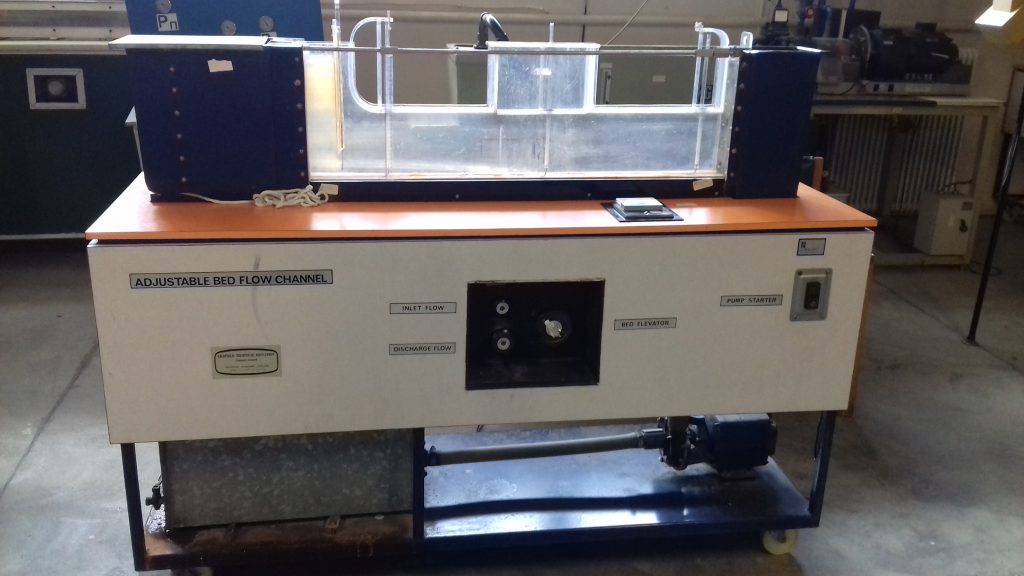
The most important feature of this equipment is the adjustable channel floor section which, together with its transition sections (ramps), may be raised or lowered by operating a control handle when the water is still flowing. This facility affords a striking demonstration of the significance of channel critical depth. When the adjustable bed section is used in conjunction with the upper boundary the result is a convergent-divergent duct of variable geometry which can be used to demonstrate the relationships between the various terms of the Bernoulli (energy) equation.
When operating in the free surface mode this apparatus is particularly suitable for demonstrating the importance and significance of channel specific energy. Change over from free surface to totally enclosed flow conditions is easily and quickly made using the control valves provided. The range of experiments is further extended by the provision of three different weirs, which can be fitted in the centre section of the channel.
The apparatus is self-contained and mobile. Sump tank, pump, flow control and metering apparatus are mounted on a steel sub-frame which carries the working section. Included are an inlet tank, containing flow stilling arrangements, and a discharge tank fitted with an adjustable overflow weir for water level control. Flow control under duct flow conditions is provided by a discharge control valve from the outlet tank. Supply of water to the working section is controlled by another valve.
The central part of the working section upper boundary is removable so that models may be installed as required. The cover incorporates a total head tube and a static pressure tapping at each of three points along the length of the working section. The total head tubes may be moved vertically over the full depth of the channel.